The Jeruino (Arduino compatible clone circuit)
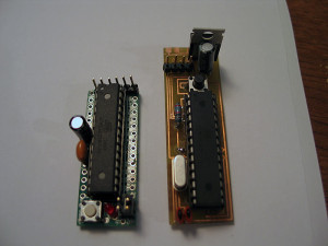
Introducing the Jeruino! (not really.. but everyone else names their Arduino knock-off clone circuit.. figured I might as well be trendy too!) LOL =)
Everyone knows how much of a whore I am for the RFX platform...
I have also been playing with the Arduino for a while too... (any member here or JSSDC can easily jump in..with both feet and be up speed (at least my speed) in a day or so...so I dont wanna hear any pissin' & moanin' about things being too hard.. lazy I'll accept)
a HUGE problem for everyone who posts this junk is 'footprint' going from the non-practical BREADBOARD set-up that is great for YouTube vids.. but not so great for any practical project.. nor is stuffing a 'real/true' Arduino board into a project (they are more development/prototyping and have alot of bells and whistles you dont need in the end) very practical and wastes money.
you can get all the components for a barebones Arduino for around $7 bucks or so.... which is much better than $30+ each time to shove in a stunt or costume or other prop..
I saw Alec post his jedi training remote.. and pm'd him saying that is great project for an RFX or Arduino 'brain'.... since it doesnt need a CF or PC..etc.. this little brains fill a nice niche.
So I opened up photoshop and got to work on making [u]my[/u] first 'real' pcb schematic (IMHO).. since this was a real working board..and not just some traces to hold sensors or switches as I have etched out before..
(I etched another 'real' board...but it was based on TroyO's schematics for a multi-channel LED driver board.. which I've posted before...PWM chopper type)
this one I created myself from scratch.. and google/instructables... (basically ported my breadboard Arduino circuit to a PCB) with the intent being fore Alec's jedi training remote.. (anyways.. not sure if that currently being worked anymore) =(
but I produced my first functioning Jeruino board.. ![]() (Arduino clone)
(Arduino clone)
Its no PlecterLabs, professionally design PCB.. etched by a PCB house...etc.. this is DIY at home... (so if your looking for that.. Alt+F4 is for you! =) )
anyways.. on with the story/post.. =)
SO I made a design in Photoshop to illustrate my traces and vias/pads..etc
you print this out on GLOSSY PHOTOPAPER.. done with a LASER PRINTER (not ink jet)

**this happens to be DUAL sided (avoid at all costs if you can..true PITA for DIY)
you cut out your traces/design... lay it over your copper clad board (RadioShack..or anywhere)
and you IRON it.. heating up the toner so it adheres and transfers to the copper board.
let sit for a few minutes.. run it under water.. and rub/peel the paper away under only traces are left on your copper board: (looks like you printed on the board... sometimes traces by the edges do NOT transfer good.. so be careful.)

cut out other side.. and get ready to repeat process:

once you have your traces transferred to the board.. it is time you etch away the visible copper.
All copper is gone.. leaving only the traces you transferred to the board left.

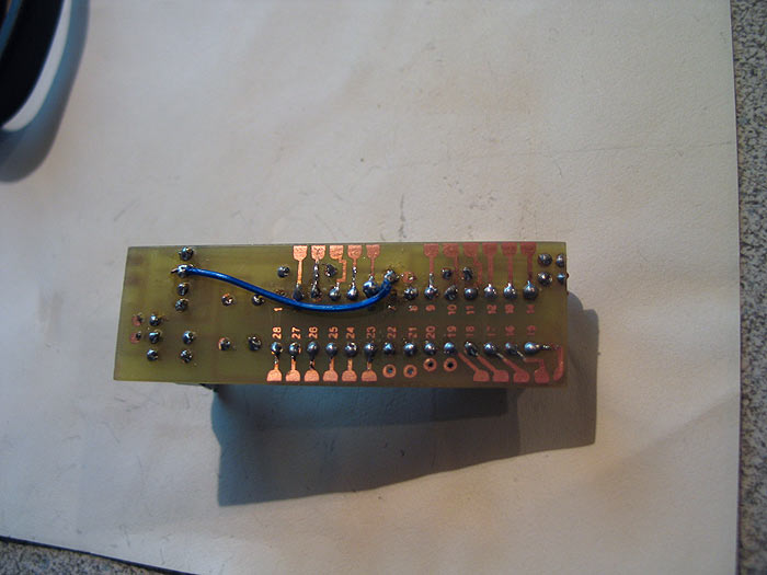
the flip side: (**warning..UGLY.. you can see the lift of the paper and traces that are crummy on this side) (you can see the holes mis-aligned a bit.. but no worries..all good)

this side came out pretty damn good though:

from here.. I removed the toner on the board with some ACETONE..


Next we drill the holes (damn there was a lot)
Doesnt look too bad (from the top)..LOL

clearer view of the bottom side with some mis-aligned holes:

what stinks about the DIY approach with dual sided.. is THERE ARE NO THROUGH HOLES PLATED.. so its a real BITCH to solder through the holes to bridge continuity..
Anyways.. once you are at this point..
you can start to solder on your components:
and....viola`


and finished product..
threw in a Atmel chip from my Arduino.. (already had a sketch/program on it..so I knew it was working)..
powered it up.. BAM.. it worked! (STOKED!)..
however.. before I posted.. I needed to check the FTDI headers.. (these 4 pin headers are how you talk and upload new sketches/programs to the chip to be 'run')...
[b][size=150]FAIL![/size][/b]
it runs...works.. but only a pre-programmed sketch that was/is on the chip.. (BOOOO!)..
who wants to buy a REAL Arduino (besides people like me).. just to swap out the chip for your final project every time your done? (I guess many people do it this way though..as FTDI takes up a little space?)
be nice to just write directly to your final Jeruino.. ![]()
so after some BS and a few swear words.. I fixed everything..(ala Ultra Sound approach) LMAO...
found a few continuity problems from top-side of board to bottom side of board..
and an FTDI problem...
the Ultra Sound fix was a missing trace to a certain pin (pin7...VCC..yikes)..
so I had to use a fix wire..like the old US boards.. hahaha.. (throw-back)
(it looks worse in the pic)
and of course.. because no good deed go un-punished and hard work is always laughed at in life..
I got punished by NOT doing my due diligence.. doing all this hard work for NOTHING!..
as I found a KIT.. that does exactly what I just created from scratch, myself.. that is MUCH more easier, and much more professional (however you dont get the satisfaction of failing over and over, swearing alot....and its missing any kind of Voltage regulator.. but making a quick PCB for that would be no problem!!!! haha)..
so I got a kit to compare mine..to 'his'... (fucker.. I really like his kits!!)
so without further ado..
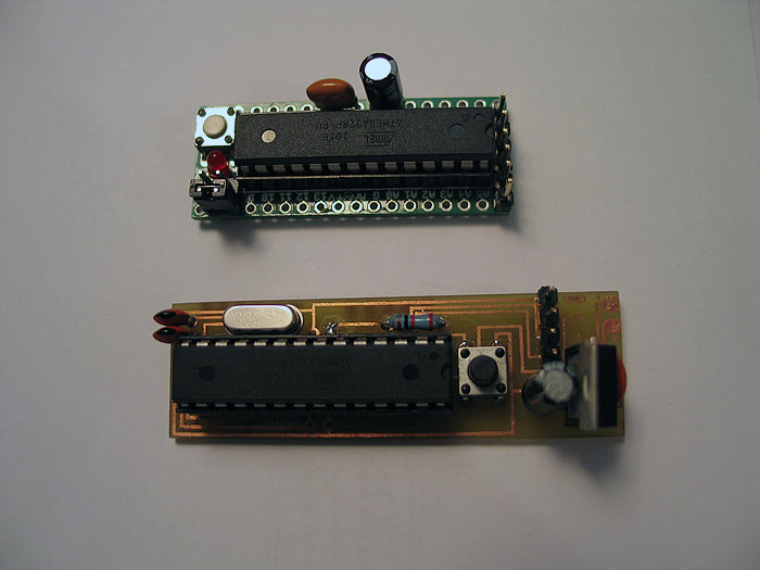
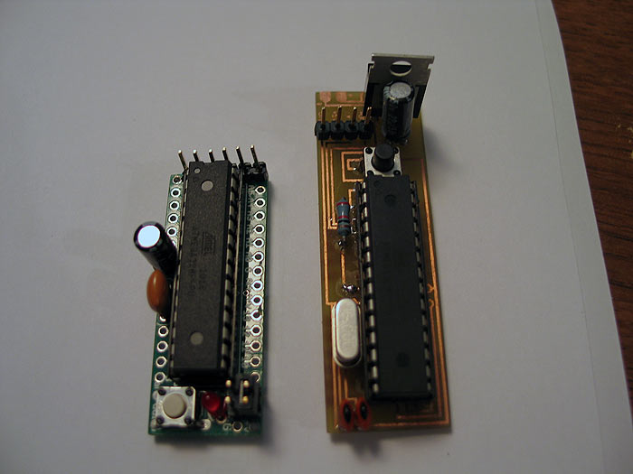
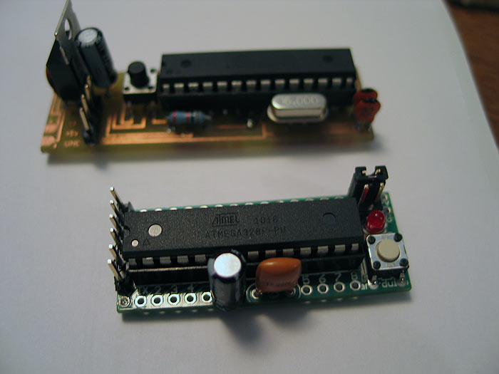
some compare pics:
my DIY vs purchased (mine has a vRegulator though..so its a bit longer)
**disclaimer-
I make no implications that I know what Im doing..
that this is the BEST approach
that this is absolutely how things much be done.
I am simply sharing what "I've" done...
but for extra $10.. it can really kick up a stunt or costume..
you have a BRAIN with MANY I/O ports to hook stuff up to..
LED's... servos/motors.. accelerometers... and the list goes on and on..
all the same brain.. just change the code. =)
hope this helps someone finish that special prop/project.
feedback or questions are appreciated.
Thanks gang..